06.05.2022
FOUNDRY FACT-FINDING
Graphic design practice is today largely desk-bound. There is limited direct interaction between the designer and client beyond a slew of emails and perhaps a Zoom meeting or two. Concepts are exchanged as PDFs for review. These on-screen representations are visually perfect, but often detached from any real-life setting and offered with little foresight as to how the digital concept may be realised. On the production side, it is rare for a designer to liaise with the manufacturer whose task is to convert final artwork into reality.
The transition to designing with software — marketed as unlocking a seemingly limitless range of creative options — has ironically fostered insular creatives. Richard Sennett's 2008 book The Craftsman foresaw this drift:
Computer-assisted design might serve as an emblem of a large challenge faced by modern society: how to think like craftsmen in making good use of technology. 'Embodied knowledge' is a currently fashionable phrase in the social sciences, but 'thinking like a craftsman' is more than a state of mind; it has a sharp social edge.
Perhaps swimming against the flow, Atelier take every opportunity to visit the manufacturers that we work with. Meeting the recipients of our artwork, understanding the work that they do to make it, and discovering other production possibilities enriches our next design project and means that we can talk convincingly to clients about any new creative challenge. The 'social edge' that Sennett mentions is also a factor in the successful completion of any project. When you know the people you work with, there is a communal interest in taking pride in what you do at every stage.
A recent fact-finding visit to an iron foundry bolstered our relationship with the craftsmen who take on our projects; nurturing an enthusiasm for new collaborations, particularly projects that may link modern technology with this long-established craft.
This blog post is a record of our findings.
TRANSMUTATION
Casting iron is the transmutation of matter; turning the alignment of atoms into new structural arrangements. Metallurgists call the conversion 'graphitisation'. I just think it fascinating, particularly when natural geometry is involved.
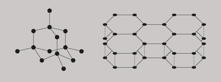
Let us start with carbon. The simplest and most common atomic arrangement for pure carbon is a diamond, where its crystalline tetrahedral structure is formed by one carbon atom bonding with only three others (above, left). Another form of carbon is graphite and whilst it is also crystalline, its hexagonal structure is a consequence of atoms bonding across a plane and in layers (above, right).
As we all know, a diamond is pure carbon and the toughest naturally occurring substance. It is a crystalline solid. Graphite, on the other hand, does not have a precise atomic shape. It is an amorphous solid. With prolonged heating of the amorphous carbon graphite, it is possible to rearrange the atomic structures to create new crystalline shapes using moulds. This graphitisation requires temperatures of up to 3,000ºC, followed by natural cooling. Both heating and cooling needs to be carefully controlled.
PATTERNS AND MOULDS
Our project was a series of wall-mounted donor plaques and the challenge was to push the known limits of the foundry's casting process — in particular, the legibility of letterforms inset into cast iron. To begin with, the two-dimensional designs existed only as digital PDFs. These had to be converted into a three-dimensional wire frame. Getting the CAD data correct at this stage was critical, as any error at this point will carry through to the final cast.
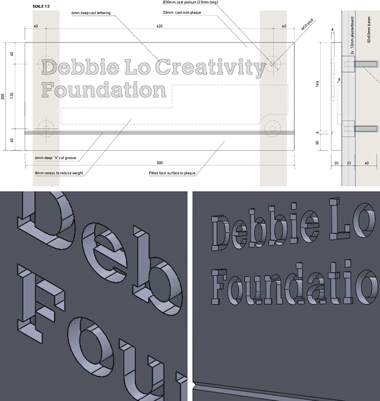
Accurately defining the dimensions of the finished plaque was obviously the main priority, but preparing a CAD pattern also includes thinking about the space surrounding the form; how the sand will be packed and how the sand moulds will be separated. A parting line needs to be established where the top part of the mould (the cope) is separated from the lower part (the drag). Internally, much thought is given to how the molten iron will flow through the mould. It will enter via a vertical hole in the cope (called a down-peg), flow through a channel (called a runner) and finally be distributed via off-shoots (called in-gates). A riser is provided as an escape for internal gas and steam generated during the pour. Lastly, an allowance has to be made for about 1% contraction during solidification and cooling.
Patterns were originally made in wood and given the accuracy involved, these often unseen, once used, and then discarded forms were works of beauty, made by highly skilled carpenters. It is not surprising that old wooden engineering patterns are now being traded by collectors for thousands of pounds. Long after cast-iron steam engines have disappeared, their wooden doppelgängers are prized fragments of long-forgotten engineering brilliance.
Our Hidden River Effra plaques were cut in pattern board (a very dense variant of MDF) using a computer-controlled router, so wood of a sort is still sometimes used. Nevertheless, pattern-making accuracy remains essential and the drawing-board blueprints and carpentry skills of old have been replaced by digital technology; 3D printing is now the future for pattern-making. Powdered polymers are laid down and laser-fused layer by layer, all guided directly from the CAD data. What took many days to fashion in wood now takes a fraction of the time to construct in thermoplastic.
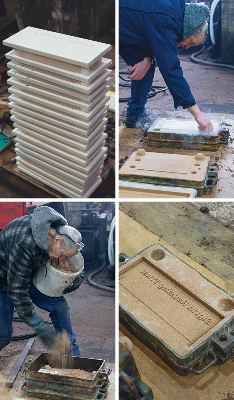
Our patterns were delivered to the foundry where Simon the moulder liberally dusted talcum powder over each of them before carefully positioning them one by one in individual mould boxes. Sand is then rammed to an even compression around the pattern. Mesmerising to watch, he deftly worked his way through the batch, preparing the cope and drag moulds for each plaque. I watched anxiously as the mould boxes were nonchalantly shifted around. Unbelievably, despite the mould boxes lacking a base, not a grain of sand appeared to stray — such was Simon's command of his medium.
While I watched Simon at his craft, Dave the foundry's foreman provided me with a brief lesson on sand, shouting over the noise of the furnace and machinery.
Mould-making sand must have sufficient plasticity to wrap around complex forms, then maintain its shape when coming into sudden contact with molten iron — and then the sand needs to collapse when the cooling iron contracts. The grain size of the sand is also a factor in making it permeable for escaping gases and moisture.
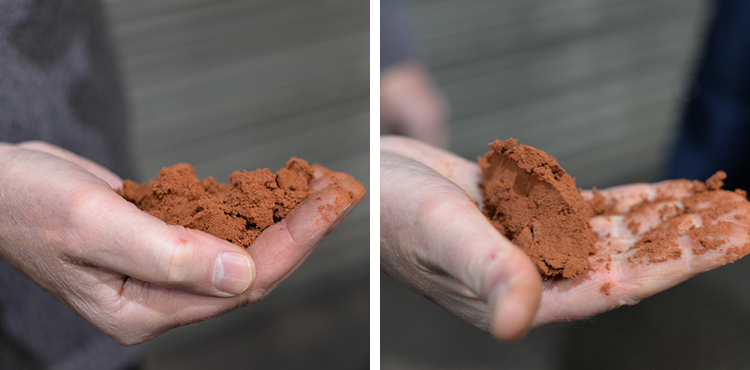
There are many types of sand used for mould-making. Dave showed me a lovely burnt orange sand, confusingly named 'green' sand. It is fine, soft and most important, it is damp; comprising 2 to 5% water to 10% clay and the balance silica sand. When held in the hand, then squeezed and released, the sand maintained its clenched form. However, our moulds were made with a different sand mix, with clay and water replaced by a resin and a catalyst that helps the sand maintain its shape after the pattern has been removed from the mould boxes. This sand mix is cleverly recycled within the foundry.
Casting iron from sand moulds has been evolving for over a millennium. Foundries around the world have used different types of naturally occurring sand, all with different qualities. It slowly dawned on me that what I was watching was the culmination of many generations working with sand — and a meticulous study of this fine-grained composition of stone and minerals. Making a perfect sandcastle on the beach will never be quite the same again.
ELEMENTS
The foundry was producing grey iron for our project. It is an alloy of iron, carbon and silicon.
The core element is pig iron, so named as it comes in ingots that are formed when the molten iron ore is poured into a sand mould fashioned with a central runner and individual offshoot runners that lead to uniform pools. This arrangement is likened to a sow nursing piglets, hence the name.
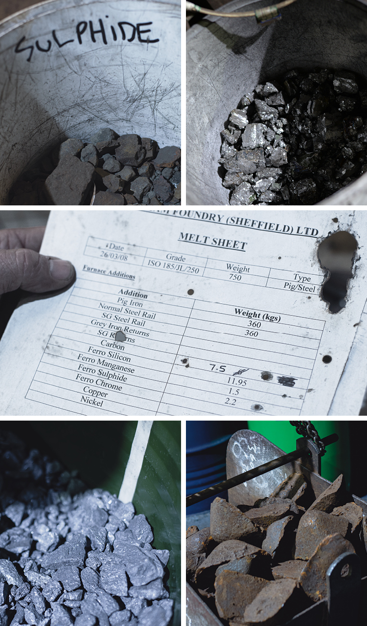
The foundry's furnace man Ian guided me closely through the smelting process. I was introduced to buckets of ore. The usual quota of pig iron (above, right), was halved for our melt mix and the balance made up with recycled steel railway tracks. Steel has a lower carbon content so the deficit was replenished by adding more carbon. Ferro silicon (top, right), is added to help the carbon transition to graphite, ferro sulphide (top, left), is added to strengthen the graphite microstructure and make the iron harder, and ferro manganese (above, left), is added to neutralise the adverse effect of sulphide, which makes the melt viscous.
The quantity of each element added to the melt mix must be precise to ensure that the alloys melt and solidify at the same temperature — known as the eutectic point. This is the lowest possible temperature at which the different elements nucleate in thermal equilibrium, forming new structural solids.
FURNACE
The furnace capacity, the ladle size and the volume of casting needs to be matched for a consistent melt, and at this foundry the eutectic point lies at 1,154ºC. Ian had many tasks to attend to while the furnace reached this incomprehensible temperature. When I asked him how he knew when the melt was ready, he replied that he could tell by eye. But for reassurance, he showed me the heat probe and predicted the current temperature. Sure enough, the probe was dipped into the melt and the reading matched his judgement.
My father was an electromagnetic engineer and so I have a rudimentary understanding of the principles of electrical charges in coils. As Ian guided me around the control panel of his induction furnace, he seemed impressed that a graphic designer understood heat transfer. Electricity passes at high frequency (up to 10,000 cycles per second) through a coil arranged around the outside of the crucible. Conductive materials such as iron have their own inherent magnetic fields and the coils around the crucible produces a contrary field. It is this motion-resistance that produces heat.
I found this a particularly ingenious use of electromagnetism. Heat is not transferred from the crucible wall to the ore, as with a conventional pot over a fire. Instead, heat is produced within the ore itself. Furthermore, when the eutectic point is reached and the melt is fully fluid, the magnetic fields generate a stirring action that can be controlled to determine the quality of the alloy. The stir is governed by the power and frequency applied, the size and shape of the furnace, the shape of the coil and the density of the melt.
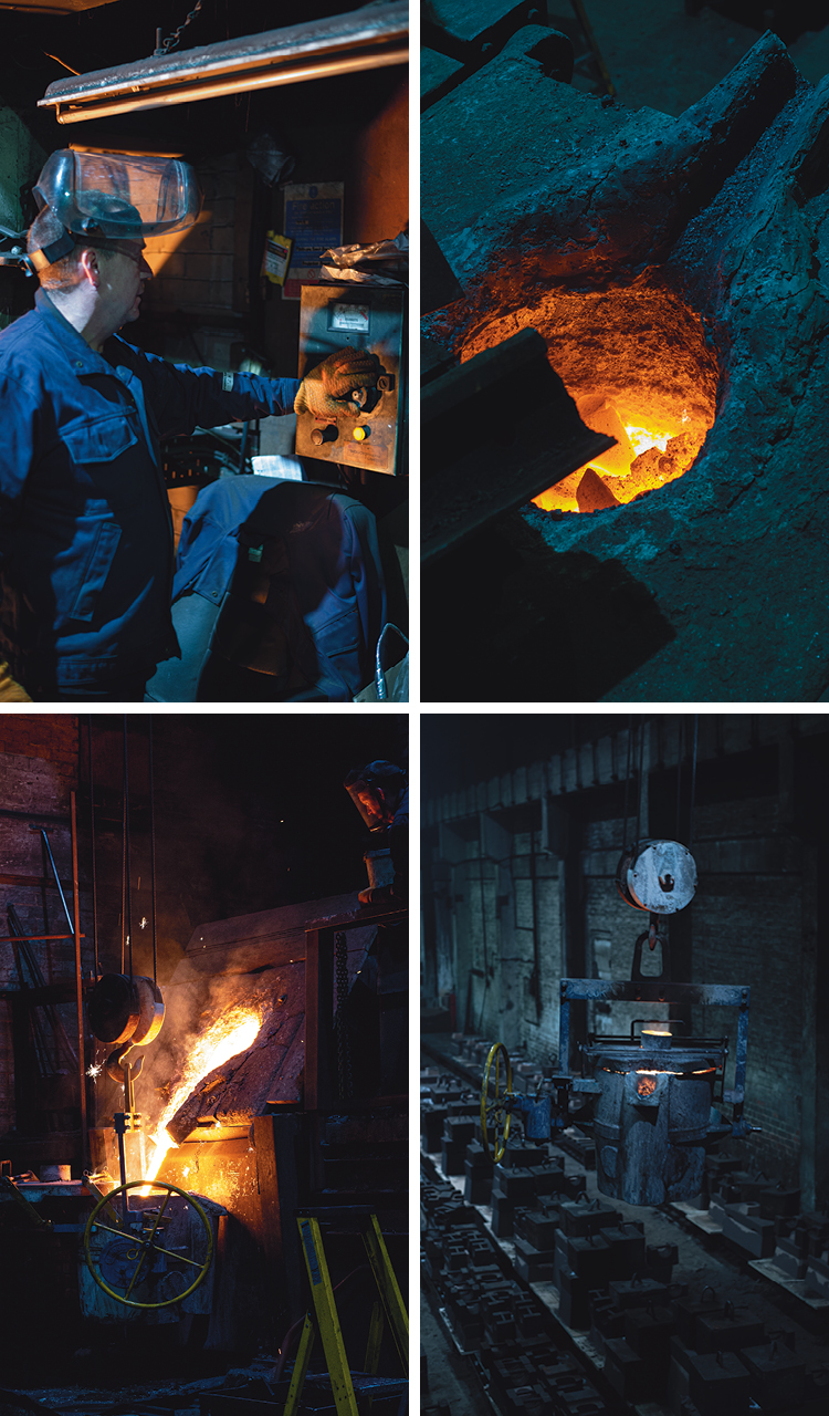
Ian kept a constant eye on his furnace — like a top chef slicing onions while also watching a simmering pot. He abruptly broke off to attend to his melt. During the smelting process, oxides rise and form a viscous layer on top of the melt; this is called slag and must be removed. Ian skilfully scooped up these impurities from the glowing surface. "Look now," he shouted as he pointed to the mouth of the furnace, "the colour of the melt has changed." It dawned on me that I'd just witnessed a real 'slagging off'.
As the melt gradually reaches the point when it is ready to be poured from the furnace (called tapping), the ladle is pre-heated to match the melt temperature. It isn't really a ladle as we would know it, rather a giant bucket suspended on chains that are attached to an overhead crane. The ladle glowed from within as it glided towards the furnace. From a safe distance I watched the furnace pivot on its yokes and decant molten iron into the ladle.
This furnace produces 750kg of molten iron. Two shifts produce 1,500kg a day. Simon is constantly busy, having to prepare just enough moulds to stay ahead of the furnace.
CASTING
The pouring temperature for cast iron is between 1,260ºC and 1,426ºC. It takes three foundry men to manoeuvre the ladle; the foreman Dave takes control of the overhead crane, Ian the furnace man handles the ladle turning-wheel, and Simon attends to the risers in his sand moulds. Again watching from a safe distance, I became engrossed in the synchronisation of the pouring team who knew exactly what to do without speaking. Their entire focus was on aiming the pour, pouring the right amount, stopping the pour and moving on to the next mould. Concentration was absolute — always watching the pour and where their colleagues stood.
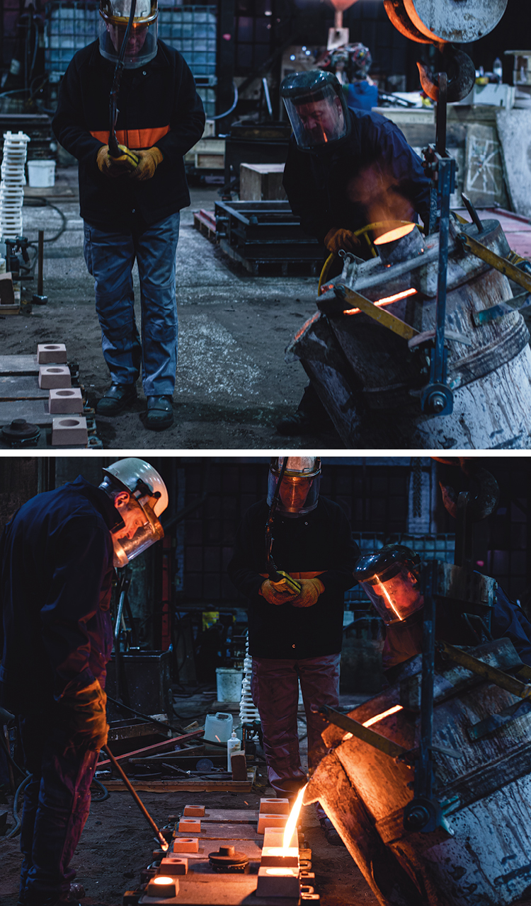
Most impressive was Ian's parabola management. Dave guided the ladle so that it was at the correct height and distance from the mould and aligned with the pouring point, now easier to see with a sand funnel (called a pouring bush) placed over the down-peg opening. Ian spun the pouring wheel to pivot the ladle forward on its trunnions. A parabola of molten iron dived from the lip of the ladle, straight into the pouring bush. It is an impressive feat to observe, given that the mouth of the pouring bush measures no more than 10cm in diameter. Ian holds the ladle steady so the pour flows without variation, and awaits a signal from Simon as the riser on the other side of the mould begins to fill. When molten iron reaches the same level in the pouring bush and riser, the parabola needs an instant cut-off; Ian spins the pouring wheel in reverse and the ladle pivots backwards to an upright position. There are no dribbles from the ladle lip and just a few spit-splashes around the mouth of the pouring bush.
The pouring team passes down the line of moulds, repeating the same precision moves until the ladle is almost empty and it is returned to the furnace end of the foundry. The ladle residue is emptied into pig moulds that will be left to cool overnight before being added back into another melt mix.
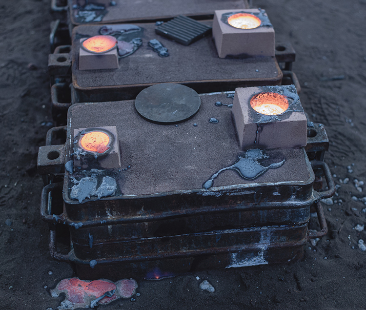
The moulds are all left with glowing pouring bushes and risers. Dave walks the line of moulds, checking his inventory. Simon returns to work on the next batch of sand casts. Ian returns to nursing his furnace.
KNOCKING OUT
Eighteen hours later, I returned to see the castings emerge from the moulds. Judging the right time to break the moulds is another acquired skill. If it is done too soon, the hot surface of the metal will react with the cool air and the structure of the iron can form carbides, becoming hard. Before breaking the moulds, all that can be seen of the casts are the pouring bush and riser holes. However, the greyness of the iron visible from these apertures is a guide to the right moment for separation.
Splitting the cope from the drag and pulling the cast from the sand is called a knocking out. It is another task for Ian while his furnace is slowly building up heat for the first melt of the day. As usual, his attention is divided between the very physical breaking apart of the moulds and listening to the hum of the furnace. Away from the furnace control panel, the audible pitch of the electromagnetic charge helps him judge what stage the furnace has reached in its temperature climb.
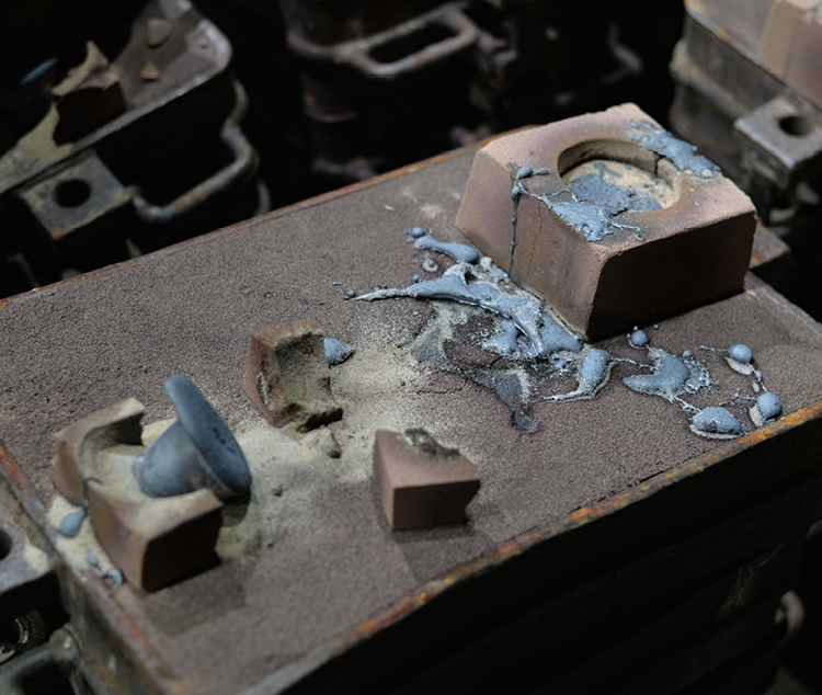
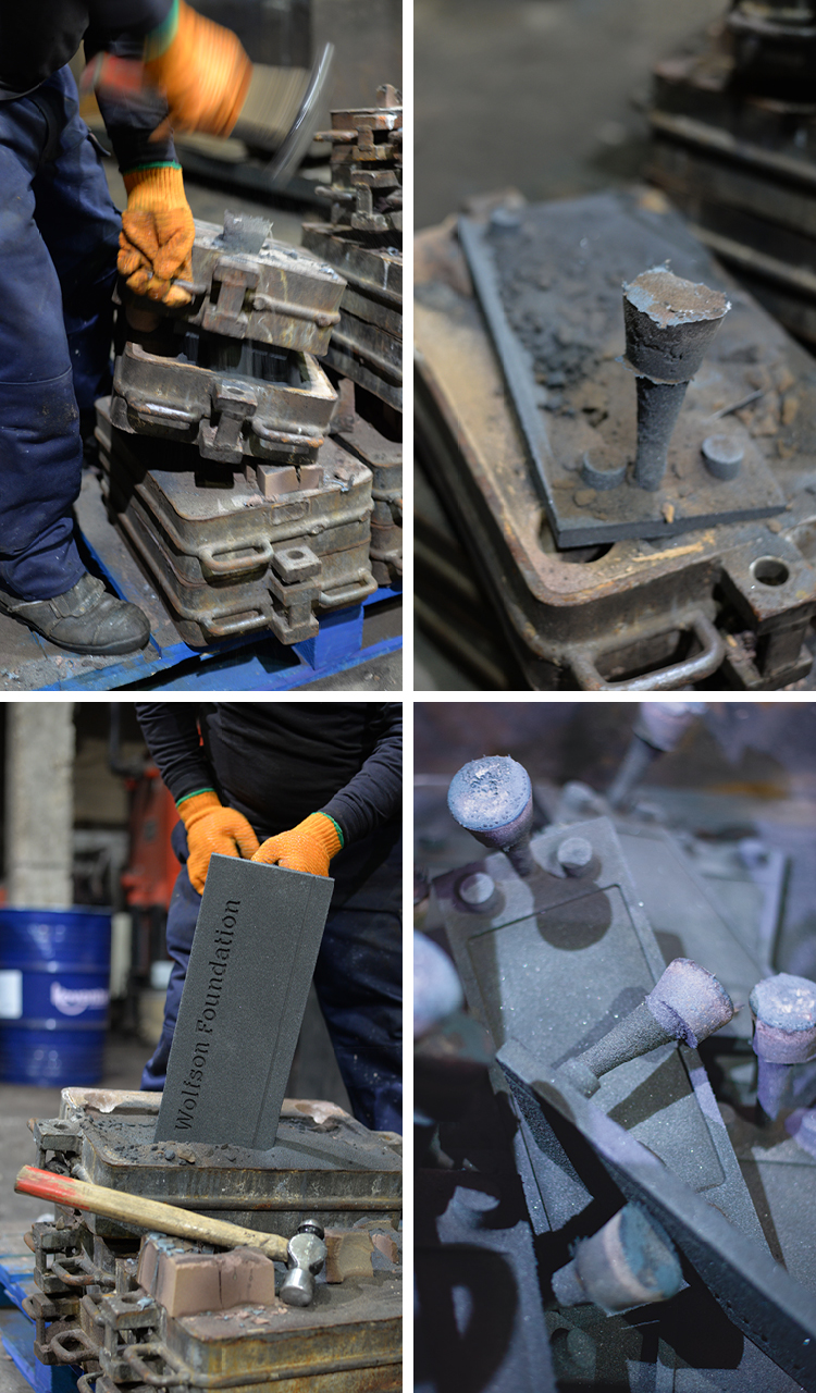
With several hefty hammer blows, the cope mould is prized away from the drag mould and the now solid down-peg is grasped to pull the cast from the collapsing blackened sand. Our batch of 22 cast-iron plaques took about an hour to extract. It was dusty, noisy and arduous work.
Ear defenders were needed when the noise level became quite deafening; the sand reclaimer vigorously shook the moulds to separate the remaining sand clinging to the cope and drag boxes. Meanwhile, our plaques with their strange down-peg and riser appendages were transported to the finishing workshop.
FINISHING
Cast cleaning is called 'fettling'. This includes the removal of the down-peg and risers. 'Burrs' also occur along the parting line of the sand mould, where small amounts of molten iron will sometimes seep out of the mould. A combination of hand-held and machine grinders cut and scrape away unwanted iron in a dramatic shower of screaming sparks. The fettlers wear respiratory equipment and clothing to protect them from high dust levels. Even so, this is a challenging environment in which to work day in, day out.
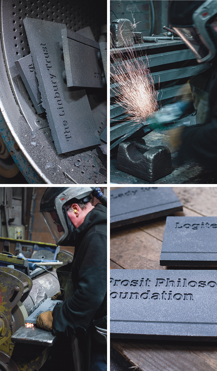
While the furnace hummed next door and the grinders screamed, our plaques clanked in the tumbler drum of the shot blaster behind us. This machine was rather like a giant spin dryer but steel shot is fired through the holes in the drum as it turns slowly. Our plaques are cleaned in the process, providing them with a stripped, even finish.
FINDINGS
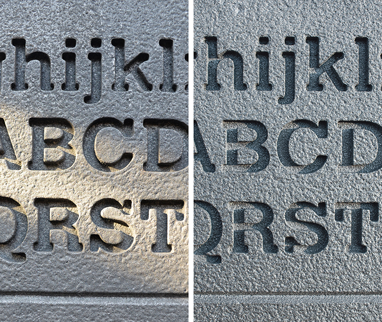
Early prototype castings provided us with some guidance on the legibility of inset letterforms:
• The lettering Calvert 107 was selected for testing. It is a wide-bodied slab serif character with low ascenders and short descenders, squared-off terminals, and large counters.
• A complete character set of upper and lower case letters was tested.
• The smallest lettering size was tested to establish how much detail could be held during sand-moulding.
• Letter-spacing was tested, to establish the minimum space between letters that could be held during sand-moulding.
• The inset depth of the letters was tested; checking how it would be affected by light fall and the resulting shadows, while remaining legible.
• Front surface texture was added to provide greater contrast with the smooth inset lettering.
Design developments made after prototyping:
• A compromise had to be made between the front inset lettering depth and the weight-saving recess on the reverse.
Summary of advances in design and manufacture knowledge:
• Successful casting of digital letterforms (type faces) is dependent on the body weight and terminal widths.
• Factors governing the sharpness of cast letters (where sharp letter outlines provide maximum legibility) include: the melt mix and the grade of sand used.
THANK YOU
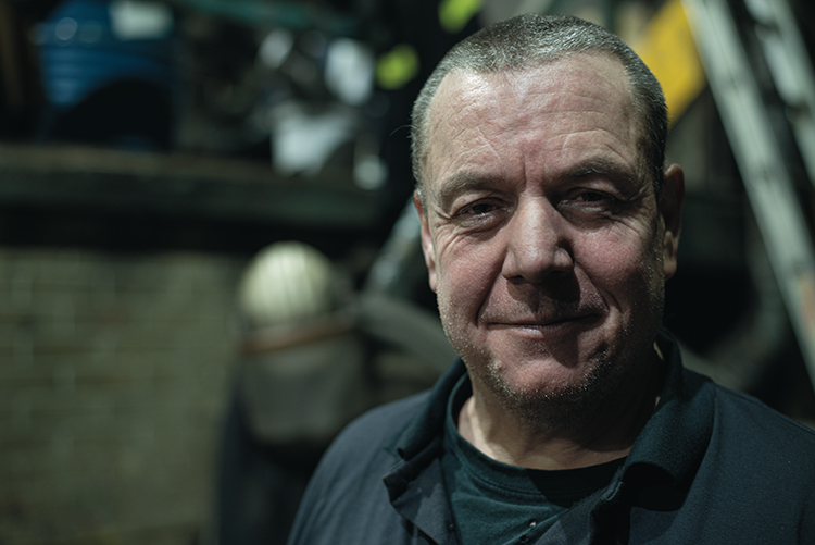
To Mike, the fourth generation owner of the family-run Durham Foundry (Sheffield) Ltd. Also Dave the foreman, Simon the moulder and Ian the furnace man (above). Their dilligence in keeping me safe and their limitless patience with me was exemplary over a day and a half of questioning.
See the finished casts for The Royal College of Art: Utilitarian signs
Ian Chilvers
![]()